Brass Tacks · May 8, 2011
Eliminating the SAN “Air-gap” requirement with FCoE and vPC
Originally posted May 8, 2011 at 12:25 AM on brasstacksblog.typepad.com/brass-tacks/2011/05/eliminating-the-san-air-gap-requirement-with-fcoe-and-vpc.html
Recovered from the Internet Archive: post and comments, captured Sep 11, 2025 · archived page (PDF)
While reading J Metz’s blog post, I noticed a comment from one of my friends at Brocade that made reference to an “Air-gap fabric” requirement and this prompted me to provide a response of my own. In my response, I briefly outlined not only what I’ll be writing about in this post, but also what I’ll be discussing during my EMC World presentation next week.
The “Air-gap fabric” requirement basically states that if two FC fabrics are used to create a redundant FC fabric topology, the fabrics should be completely (physically and logically) isolated from one another, or in other words, separated by an air gap. To be fair, until recently, I was a proponent of this approach (at EMC, we call it SAN A / SAN B) and I probably would have treated suggestions to break this best practice with contempt… However, after having had the opportunity to configure and test vPC in our lab and see first hand the benefits it can provide, I’ve been thinking that I need to revise my stance slightly, at least when it comes to the definition of logical isolation.
For those of you who haven’t had a chance to use it, vPC or virtual Port Channel allows for two Cisco Ethernet switches to appear as a single physical chassis to a third device such as a host. In the example shown below, Ethernet Switch / FCF 1A and 1B have been configured to be members of the same vPC domain and have been directly connected together via a vPC peer link. The NIC/CNA connections from the host are each connected to a different switch and the switch ports they are attached to have been configured to be a part of the same virtual Port Channel. Once this is done, the switch will appear to the host as a single chassis from a Layer 2 Ethernet (not including FCoE) perspective.
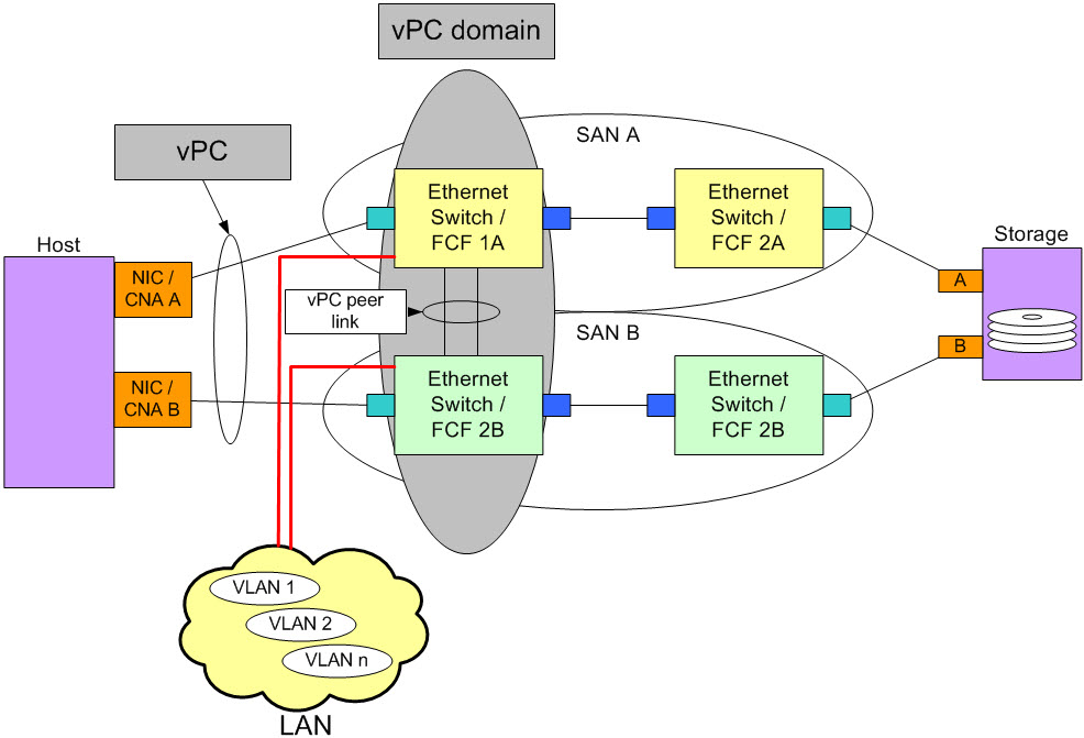
Figure 1
This is a very powerful concept because it allows a host to use active/active NIC teaming (or bonding with Linux) while still being connected to two physically separate switches thus avoiding a single point of failure due to a hardware malfunction. Another nice feature of vPC is that since FCoE Frames are explicitly prohibited from crossing the vPC peer link, it allows the SANs to remain logically isolated preventing not only a single point of failure due to a software bug in the FC code but also preventing a loss of connectivity due to a well intentioned but ultimately misguided attempt to make an administrative change to something like FC fabric zoning.
When I set this configuration up in the lab I noticed a number of interesting things:
- First was the fact that even though I had created a team and only had a single vNIC, the storage stacks (FCoE functionality) on each CNA remained separate from one another, see figure 2 below. This wasn’t actually surprising but the fact that it was done this way allows our multi-pathing software (PowerPath) to continue to function normally.
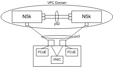
Figure 2
- Since there were still two FCoE Adapter instances, I still had two unique WWPNs and as a result, there was no impact to Fabric zoning.
- Another interesting point was that when I created the vFC on the 5548s, I had to bind them to the virtual port channel. While this worked fine when connecting to two different 5548s, if you connect both CNAs to the same 5548 and attempt to do the same thing, it will not work properly and only one of the CNAs will be allowed to complete FCoE login by the switch. I don’t view this as a problem and believe everything is working as designed. The only reason I did it this way was to troubleshoot a vPC issue and wanted to remove the second vPC chassis from the configuration. I ended up making the configuration so simple that it actually didn’t make sense anymore. Sort of like trying to troubleshoot a LAG related problem with only one link…
- For testing purposes, we ran block I/O over FCoE and file I/O (CIFS) simultaneously and then performed some cable pull testing to ensure that failover and failback would work properly. I was happy to observe that for both block and file I/O it worked very well.
For more information on configuring vPC with FCoE, see the FCoE TechBook.
The downside to this configuration is that it requires a bunch of additional administration steps and in my experience it makes troubleshooting a bit more complex. However, if you need to use active/active teaming in your converged network, the additional complexity may be worth the extra work.
An interesting development with this type of configuration, recently released by Brocade, is Virtual Cluster Switching or VCS. VCS will eventually allow for the topology like the one shown in figure 1 but it will mostly self configure and this will drastically reduce the administrative burden of creating such a topology. EMC is currently working with the VDX switch / VCS feature and should be announcing a supported topology sometime in the near future.
Adjusting the “Air-gap” requirement
Since the topology shown in figure 1 allows a host to connect to physically separate switches and for the FC fabrics to remain logically isolated, I don’t believe the SAN A / SAN B principle is being violated. As a result, I don’t believe an adjustment to the SAN A / SAN B best practice is required. Rather, I think we need to consider a redundant fabric topology in which some of the switches are logically joined by a separate protocol such as vPC or VCS, as a valid redundant fabric topology that can be used in a converged network environment. That having been said, I’d like to hear your thoughts…
For more information…
As I mentioned in a previous post, I’ll be presenting at EMC World this year. My presentation was originally going to be an updated version of last year’s but I ended up almost completely re-writing the entire slide deck. This year I’ll be talking about:
- the “Air-gap fabric” requirement
- the updates to our supported topologies
- the impact the release of FCoE on director class products and the introduction of VE_Ports have had on the supported topologies
- three “real world” converged network use cases. One of the converged network examples will cost almost 60% less than the non-converged reference topology I’ll be providing and use only 60% of the power!
If you’re interested in attending, I’ll be presenting on Tuesday from 5:00 to 6:00 and on Wednesday from 4:15-5:15. Also, there will be a Future of Storage Networking “Birds of a Feather” session on Wednesday morning from 8:30 – 9:30.
Hope to see you there!
Thanks for reading!
Comments (3)
-
BRCDbreams · 05/09/2011 at 01:33 PM
-
BRCDbreams · 05/09/2011 at 01:57 PM
Erik,
And one other point I forgot to add to my earlier comment. I think my argument about FC routing preserving the air gap for the control plane meant that FC routing preserved the the air gap design goal of more than one independent control plan for storage traffic.
IF you agree with that, AND, IF you further think your design for FCoE w/ vPC provides at least two independent control plans for FCoE traffic, then I'd say the title of your article would become "Emulating the SAN air gap for FCoE with vPC".
Last, can vPC support more than 2 switches as we can with FC Routing? If so, that would provide good scalability.
-
Erik Smith · 05/10/2011 at 01:09 AM
Hi Brook, interesting point about FC Routing. I had originally considered including that concept to support my claim about vPC and VCS, but it opens a can of worms that I haven't fully thought through let alone tested in the lab.
If we are talking about a stand alone Brocade FC Router that contains EX_Ports, then with Brocade's implementation, I am fairly comfortable with the idea since the EX_Port was described to me by one of your Engineers' as a light E_Port that accepts configuration information from the fabric. Thinking about it now, the exceptions are probably SW_RSCNs and probably E_Port specific frames like HLO, etc but I'm sure you know more so than I. In any case, given that the EX_Ports aren't pushing configuration information to both fabrics, I'm OK with the idea but would want to get into the lab and validate before signing off on the idea completely.
With the other implementations, or when the routing capability is build into one or both of the switches that are participating in the fabric, I'm not ready to sign off on the concept yet. To be completely honest, my hesitation is due more to a lack of knowledge about the internals of Brocade's Integrated Routing and Cisco's IVR rather than specific knowledge about any particular problem. That having been said, I'd be open to the idea if either of them truly isolates the SANs from one another.
To answer your other questions, vPC is currently limited to two switches and I'm not sure if this will change or not going forward.
If we only disagree about the title of the blog post, I think we're in pretty good shape!!
The comments to this entry are closed.
Erik,
First, full disclosuer, I work for Brocade.
Thanks for showing this implementation of FCoE isolation. As I look at this, I think an argument can be made that in a lot of ways the isolation afforded is reminiscent of the isolation achived when using FC routing with multiple FC fabrics. With FC routing, each fabric control plane (and zoning and other policies) remains independent so Mr. Murphy-based configuration errors can't propogate beyond a single fabric. A good thing.
For those reasons, FC routers, properly implemented, are seen as preserving the air gap architecture for fibre channel fabrics.
I'd appreciate your thoughts on that.
And, indeed simplifing configuration steps would be a virtue, so I'm interested in your experience with the Brocade VCS Ethernet fabric when you test that.